Introduction
Contents
Introduction#
There’s still much to do;
still so much to learn.
Mr. La Forge - engage!
—Captain Jean-Luc Picard
A brief history#
Edward Ardern and William T. Lockett are widely recognized as the inventors of the activated sludge process [Jenkins and Wanner, 2014]. Their discovery was that the retention of sludge in a reactor greatly improved the reaction rates in the nitrification process [Adern and Lockett, 1914]. The set-up they used in their experiments was very similar to what we use today for research of AGS. They would fill a bottle of 2.4 L, with biomass and influent. Then after aerating the bottle for multiple hours, the mixture was allowed to settle and the clear effluent was decanted. The biomass was retained in the bottle and fed the next batch of influent. They found that sludge retention was an important mechanism for activating the sludge. Looking back, they came surprisingly close to the invention of Aerobic Granular Sludge, but history tells us that it took more than 80 years for this fact to happen [Heijnen and van Loosdrecht, 1998, Morgenroth et al., 1997]. The main reason for this might be the absence of automated valves that made the use of full-scale fill-and-draw batch systems almost impossible for many decades to come and for this reason the world moved towards continuous flow systems [Jenkins and Wanner, 2014].
I will not try to cover the full history of aerobic granular sludge - others already did do a good job at this [Pronk, 2016, Pronk et al., 2020]. But there are some key developments in wastewater treatment I need to address, that made the discovery of AGS possible. As the reader will notice, this dissertation is for a large part about the differences and similarities between conventional activated sludge and AGS. There are a few key mechanisms that are important for growing AGS, which are discussed in detail in chapter On the mechanisms. One of the marker points in the history of aerobic granular sludge was the discovery of anaerobic granular sludge. In the early 1970’s the Dutch sugar factor CSM worked together with the Landbouw Hogeschool Wageningen, to develop a compact solution for anaerobic treatment of wastewater from sugar beet processing. This led to the development of the UASB [Lettinga et al., 1975]. In the decades after the discovery of anaerobic granular sludge the technology was rapidly adopted worldwide and new concepts like the Expanded Granular Sludge Bed and Internal Circulation reactors were introduced. Meanwhile the search for aerobic equivalents of these technologies started. First successes were made with biomass on carrier systems [Heijnen et al., 1990, Heijnen et al., 1993]. In these biofilm suspended carrier systems similar physical properties were reached as we now know from AGS: terminal settling velocities of 50 m h-1, volatile suspended solids of up to 40 g L-1 and superficial velocities in the clarifier up to 30 m h-1. In this same period researchers started to understand that the morphology of the aerobic biofilm resulted from a balance between biofilm loading rate and shear rate (or a balance between growth and detachment) [van Loosdrecht et al., 1995]. Mathematical modelling also showed that a balance between substrate uptake rate and transport rate was necessary to form a smooth and stable biofilm [Picioreanu et al., 1998]. If the substrate uptake rate is lower than the transport rate, this would lead to uniform bacterial growth throughout the biofilm, while the opposite case would lead to an unstable biofilm.
The first proof of concept of aerobic granulation was reported in 1998 [Heijnen and van Loosdrecht, 1998, Morgenroth et al., 1997]. These granules were grown in an SBR with molasses as substrate and the SBR was operated completely aerobic, without an anaerobic feeding phase. Applying a selection pressure between 30 and 40 m h-1 led to granules with an average diameter of 2.35 mm and a terminal settling velocity of almost 40 m h-1. Long term stability of the granules was found to be problematic, so further research was necessary. After this historic moment, the scientific world embraced the AGS technology and research really took off, as can be seen in figure Fig. 1, showing the increase of scientific publications on AGS over time.

Fig. 1 Yearly publications on aerobic granular sludge since the invention (1997-2021). Source data retrieved from https://www.scopus.com.#
From research in the 2000’s it was concluded that slower growing organisms will form granules more naturally than fast-growing organisms [Martins et al., 2004]. It was also recognized that the conversion of rapidly biodegradable substrates into slowly biodegradable stored substrates by applying an anaerobic feeding phase and an aerobic famine phase, greatly improved the granule stability and removed the need for high shear forces [de Kreuk and van Loosdrecht, 2004]. The feast and famine regime resulted in microbial selection of organisms capable of storing acetate as PHA, such as PAO and GAO. This approach effectively made the split between the transport of substrate into the biofilm and the growth of the biofilm, introducing a perfect balance between these two mechanisms. This step made the technology ready for adoption by the industry and shortly after this, in 2005 the first full scale application was built: a 250 m d-1 Nereda® reactor at the Vika cheese factory in Ede, The Netherlands [Giesen et al., 2013]. After this first market introduction, gradually more full-scale installations were built (see also the next section).
Benefits of AGS#
So, what are the advantages of AGS over conventional activated sludge flocs? For a large part, AGS is similar to activated sludge. One can find the same species in an aerobic granule as in an activated sludge floc [Ali et al., 2019], although maybe in different ratios. Also, the species distribution is different in different granules sizes. It was shown by Ali et al. [2019] that for example, Ca. Accumulibacter phosphatis is more enriched in the largest granule sizes. This is to be expected because the current AGS reactors are fed from the bottom of the reactor, favouring the largest granule fraction with readily biodegradable substrates (see chapter On the mechanisms), used by PAO. Because of the similarities between granules and flocs, many processes will be similar. There are three major differences that make the use of AGS advantageous:
The good settling properties of AGS
The dense biomass and related biofilm properties
The production of biopolymers with special properties
The settling properties of AGS are very different from the settling properties of conventional activated sludge flocs (chapter Settling behaviour). Activated sludge flocs will settle bulk-like, meaning the sludge bed will behave very much like one coherent entity, while AGS will settle as discrete particles. This results in a distinct separation between the sludge phase (the granules) and the water phase (outside the granules). Individual granules can settle with settling velocities up to 100 m h-1, but in a sludge bed the actual settling velocity is (much) lower because of interactions between the granules. Nevertheless, the settling properties of an AGS sludge bed are much better than the settling properties of a bed with activated sludge flocs. Superficial flow velocities in an AGS reactor can be 5-10 times higher than in a secondary clarifier. As a result, the process of liquid/solid separation through gravity induced settling is much faster with AGS than with activated sludge flocs. In CAS installations liquid/solid separation is typically done in a separate tank (secondary clarifier), or a separate phase in the case of a conventional SBR (settling and decanting phase), consuming a lot of surface area. In AGS the liquid/solid separation is started in a short settling phase at the end of the cycle, but mainly takes place during the simultaneous feeding of influent and decanting of effluent. As a result, the liquid/solid separation will only add about 10 % to the AGS reactor volume.
Aerobic granules grow in dense aggregates, with a typical biomass concentration of 35 to 50 kg m-3. Because of voidage between granules, a settled sludge bed can have a concentration of 25 kg m-3. A typical biomass concentration in an AGS reactor is 8 kg m-3, but values over 15 kg m-3 can be reached in practice. This means the biomass concentration often is not the limiting factor in the AGS process. For example, a temperature drop will not decrease the nitrification rates of an AGS reactor as much as in a CAS system [de Kreuk et al., 2005], because of an abundance of nitrifiers in the biomass. The thickness of the biofilm also allows for anoxic conditions in the centre of the granule during aeration, making it possible to nitrify and to denitrify during aeration. Activated sludge flocs are fully penetrated with oxygen much quicker, often making it necessary to build separate denitrification tanks. With AGS denitrification can for a large part take place simultaneously [de Kreuk et al., 2005]. It is therefore often not necessary to apply a denitrification phase, which is the CAS equivalent of not building a denitrification tank.
Recourse recovery is an important aspect in wastewater treatment nowadays. It was found that the extracellular polymeric matrix of AGS (Kaumera) can be recovered to produce novel materials. Although in activated sludge flocs similar polymers can be found, the gel-forming properties of polymers found in AGS form an interesting new resource. Low end application of these polymers can be found in agriculture (plant growth stimulant), but also potential high-end application such as flame retardants and high strength composite materials are already produced in the lab [Pronk et al., 2020]. Research showed that about 25 % of the organic biomass of AGS consists of these polymers and can be used for all sorts of applications [Kim et al., 2020, Pronk et al., 2017]. So in the near future, wasting of biomass of an AGS reactor becomes harvesting of biomass. And this future is already here. The first full-scale recovery unit was built in Zutphen and opened in 2019. Here a dedicated Nereda® plant is built, treating wastewater from a dairy industry, with the sole purpose to produce AGS for polymer extraction.
Nereda technology#
In this dissertation I often used data and biomass from pilot-scale and full-scale Nereda® reactors. Nereda® is the brand name of the aerobic granular sludge technology developed by Royal HaskoningDHV, which is also the company I was working for during the PhD research. After the first successful introduction in the dairy industry in 2005, several other industrial applications followed, as well as the first small municipal wastewater treatment plants. The next marker point in the history of Nereda® was the start-up of the first full-scale municipal plant in Epe, the Netherlands. The opening of the Nereda® plant in Epe generated a lot of national and international publicity, accelerating Nereda® development. Two years later, in the period 2013-2014, another 4 Nereda® plants were constructed in the Netherlands: Garmerwolde, Vroomshoop, Dinxperlo and the PNU. The Garmerwolde plant was a breakthrough in size. With a design capacity of 140000 p.e. it was larger than all previous Nereda® plants combined and the first one larger than 100000 p.e.. The PNU later became the primary research facility for municipal wastewater based aerobic granular sludge research and many of the experiments described in this dissertation were performed at this location. From this time forward more and more Nereda® plants were built, spanning over all continents (except Antarctica) - see Fig. 2.
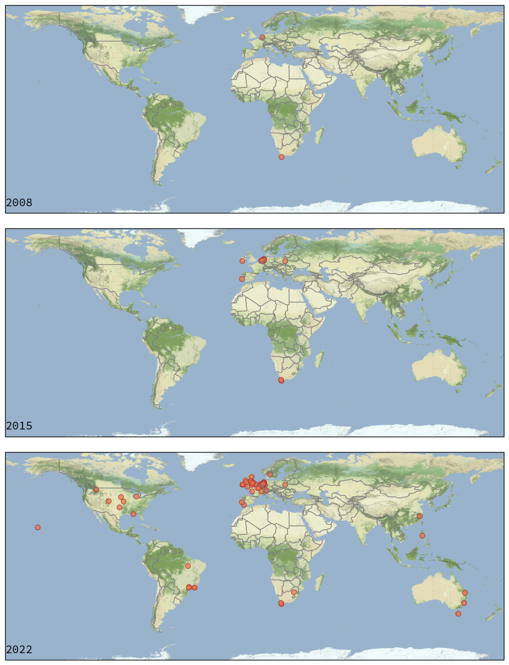
Fig. 2 Full scale Nereda® plants over time; 6 in 2011 and 91 plants in operation or under construction in 2022.#
A Nereda® reactor is a SBR, in contrast to conventional continuous flow-through reactors with flocculent activated sludge. A mathematician would say that the difference between a SBR system and a flow through system is that the dimensions are interchanged. In a flow-through system the different process conditions (anaerobic, anoxic and aerobic) are separated in space and (more or less) constant over time. In an SBR system the process conditions are separated in time, but are applied in the same reactor. This is shown in Fig. 3. Here the MUCT process is compared with the Nereda® process. In the mUCT process biomass is recycled back to the anaerobic reactor, for fermentation and uptake of VFA from the influent. In this anaerobic reactor, polyphosphate is degraded as an energy source for the uptake of VFAs. Then the biomass together with the influent, flows into the anoxic tanks for denitrification (and some phosphate uptake) and subsequently into the aerated reactors, for nitrification, phosphorus uptake and COD removal. Separation of the purified water and the biomass happens in the secondary clarifier. The thickened sludge is pumped back to the first anoxic tank. All of these process steps can be found in the Nereda® process. The anaerobic contact between biomass and influent happens when the reactor is fed from the bottom into the (settled) sludge bed. Because of the plug flow feeding, there is limited mixing of purified water from the previous batch and the influent, allowing for anaerobic conditions. After the feeding phase, the tank is aerated. The thickness of the granular biofilm allows for SND and in many cases no separate anoxic phase is necessary. If necessary, a pre-denitrification or post-denitrification phase can be applied. The separation of the purified water and the granular sludge is done in the settling phase.

Fig. 3 Comparison of a continuous flow-through system (A) with a sequencing batch system (B).#
The Nereda® cycle has three main phases, the feed and decant phase, the reaction phase and the settling and wasting phase. Feeding and settling happens simultaneous, as opposed to conventional SBR systems where feeding and decanting are separate phases. Feeding and decanting can be done simultaneously because of the advantageous settling behaviour of the AGS. At the superficial flow velocities applied in Nereda® (up to 5 m h-1), conventional activated sludge would washout with the effluent. The settling properties of AGS (see chapter Settling behaviour) allow for a good separation between biomass and purified water during the feeding phase. The plug flow feeding regime causes a limited contact between fresh influent and purified water from the previous batch, and at the same time ensures good anaerobic contact between influent and the settled sludge bed. Readily biodegradable COD is taken up by the biomass, releasing phosphate in the process, because of the EBPR process. In the reaction phase, aerobic and anoxic conversions take place. The reactor is aerated, and COD and ammonia are oxidized. Through the process of SND (part) of the nitrate formed is converted into nitrogen gas. Phosphorus is also removed because of the uptake of phosphate by the PAO. For extra nitrate reduction sometimes pre- or post-denitrification phases are added to the reaction phase. More advanced methods for optimizing SND are also available [van Dijk et al., 2020]. The settling and wasting phase often starts with a short period of aeration to strip dissolved nitrogen gas from the water phase (chapter Suspended solids). This aeration also mixes the biomass in the reactor. After a short settling period (depending on the applied selection pressure), the top of the sludge bed is wasted. Only the top of the sludge bed is wasted, allowing for selectively discharging flocs and other bad settling sludge from the sludge bed (see also chapter On the mechanisms). After this the cycle starts over with simultaneous feeding and decanting.
Most Nereda® plants have 2 or more reactors. This is because most plants must take in wastewater continuously. In the reaction phase, and the settling and wasting phase, a reactor cannot receive influent. To overcome this problem, multiple reactors can be scheduled is such a way, that 1 reactor is always available to receive influent. This method of scheduling relates the feeding time to the number of reactors and the time available for reaction and settling. With only 2 reactors the feeding time will become equal to the time for reaction and settling, making the reactors relatively inefficient. With 3 or more reactors this is less of a problem. A solution for this inefficiency is application of an influent buffer. This allows for an interruption of the continuous feeding and an efficient reactor scheduling, also with 1 or 2 reactors available [Pronk et al., 2020]. Under DWF a different scheduling is used than under RWF. Under dry weather conditions the scheduling is defined by the conversion rates, while under rain weather conditions the hydraulics (maximum batch size and up-flow velocity) determine the phase times. An example of different scheduling between DWF and RWF is shown in figure Fig. 4.
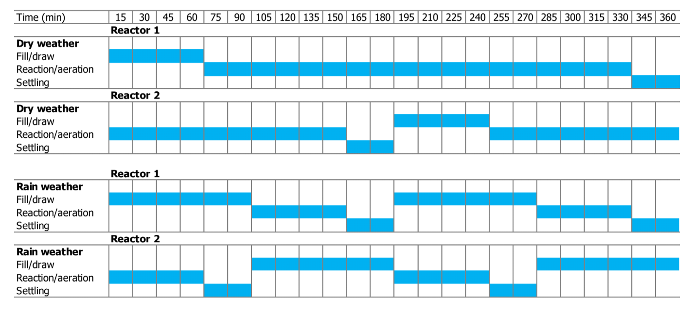
Fig. 4 Example of a cycle of a Nereda® plant with an influent buffer for storage of influent between feeding phases during DWF. Continuous feed during RWF conditions.#
Nereda® plants used in this research#
In this dissertation measurements have been done on different locations, with sludge from multiple Nereda® reactors (see Table 1).
The Nereda® in Garmerwolde is a municipal wastewater treatment plant, owned by the Dutch district water authority Noorderzijlvest and is operated since 2013. It consists of 2 Nereda® reactors and an influent buffer and it has a design capacity of 140000 p.e..
Utrecht has two Nereda® plants, the full-scale of Utrecht and the PNU. The full-scale installation is a municipal wastewater treatment plant, owned by the Dutch district water authority HDSR and it is operated since 2018. It has a design capacity of 430,000 p.e. and it consists of 6 Nereda® reactors and an influent buffer, each of 12,000 m3.
The Prototype Nereda® Utrecht is a municipal wastewater treatment plant, owned by the Dutch district water authority HDSR and it is operated since 2013. It consists of 1 Nereda® reactor of 1,000 m3 and is operated at variable sludge loading rates. Since 2016 it is used as a facility for full-scale AGS research by RHDHV.
The Nereda® plant in Dinxperlo has 3 reactors and a small influent buffer. It is owned by the Dutch district water authority Waterschap Rijn en IJssel. The plant was designed for 15,730 p.e..
In Vroomshoop the first hybrid Nereda® reactor was build. It is owned by the Dutch district water authority Waterschap Vechtstromen and it is in operation since 2013. In the hybrid concept, AGS waste sludge is spilled into the nearby CAS plant. This is done to improve the sludge characteristics of the CAS system. The Nereda® plant in Vroomshoop consists of 1 reactor and an influent buffer.
The Nereda® plant in Epe was the first full-scale municipal AGS plant in the Netherlands. It is owned by the Dutch district water authority Waterschap Vallei en Veluwe and it is in operation since 2011. For the large part it receives domestic wastewater, but a considerable part of the influent comes also from slaughterhouses.
plant |
geohash |
volume |
capacity |
water authority |
|---|---|---|---|---|
Prototype Nereda Utrecht |
u178kq8 |
1,000 |
- |
De Stichtse Rijnlanden |
Nereda Utrecht |
u178knt |
6 x 12,000 |
430,000 |
De Stichtse Rijnlanden |
Nereda Garmerwolde |
u1kwzvt |
2 x 9,500 |
140,000 |
Noorderzijlvest |
Nereda Vroomshoop |
u1kdm7s |
1,340 |
22,600 |
Vechtstromen |
Nereda Dinxperlo |
u1hwgpz |
3 x 1,250 |
15,730 |
Rijn en IJssel |
Nereda Epe |
u1k3b88 |
3 x 4,500 |
53500 |
Vallei en Veluwe |
About this dissertation#
Aerobic granular sludge technology is becoming a widely accepted technology for wastewater treatment. Although it is widely accepted and soon the 100th full-scale treatment plant will be built, there are still many discoveries to be made. Mechanisms and fundamentals that are common ground for flocculent activated sludge are still undiscovered lands for aerobic granular sludge. In this dissertation I aimed to fill in a few of the important knowledge gaps we face in design and operation of AGS technology.
In chapter Effluent suspended solids the topic of effluent suspended solids was explored. In the first 15 years of AGS development the amount of suspended solids in the effluent of AGS reactors received little attention. This is mainly because the process conditions and the hydraulics of lab scale reactors are very different from full-scale reactors and lab reactors are mainly designed for optimal biological conditions. In the first full-scale installations effluent suspended solids were not a topic, because it concerned industrial installations discharging effluent to the sewer. The first full-scale domestic AGS plant in the Netherlands was Epe, which due to discharge to a small river needed post-treatment (sand filtration) of the full flow, to remove all solids from the Nereda® effluent. Only when more full-scale installations were built did it become clear that the concentration of effluent suspended solids could become too high. It was shown that degasification of nitrogen gas and wash-out of bad settling particles were the major source for these elevated concentrations and it could be solved relatively easily. In this chapter the mechanisms behind the degasification of nitrogen gas were explored. It was shown that effluent suspended solid concentrations comparable with CAS could be achieved with an AGS reactor.
In chapter Settling behaviour the settling behaviour of AGS was explored. As described above, the advantageous settling characteristics of AGS are a fundamental part of the technology. In previous research it was shown that individual granules can settle very fast, but in practice it is not about individual granules, but about the behaviour of the sludge bed, with interactions between trillions of individual granules. The settling behaviour of activated sludge is well described with widely accepted mathematical models. These models generally describe the behaviour of the sludge bed based on 1 sludge phase and a bed going through regimes of particulate settling, zone settling and compression. In AGS the particle coherence is much more discrete, demanding a different mathematical approach to describe the settling behaviour. In this chapter this different approach was combined with validation based on full-scale measurements.
Nitrous oxide is a gas commonly emitted from wastewater treatment plants, as a side product from nitrogen removal. Since nitrous oxide is a strong greenhouse gas, emission from wastewater treatment plants contributes to global warming. A long-term measurement campaign was performed in a Nereda® reactor at the wastewater treatment plant in Dinxperlo. In chapter Nitrous oxide emission, the dynamics of nitrous oxide emissions are explored.
How do aerobic granules grow? That is the question asked in chapter On the mechanisms. After more than 20 years of research we know how to grow granules, but we lack an in depth understanding of how they grow. In this chapter we proposed 6 fundamental mechanisms leading to growth of aerobic granular sludge. A mathematical model was made to show the importance of the different mechanisms.
Where do we go from here? The journey of AGS is only starting. We will explore the future in the Outlook.